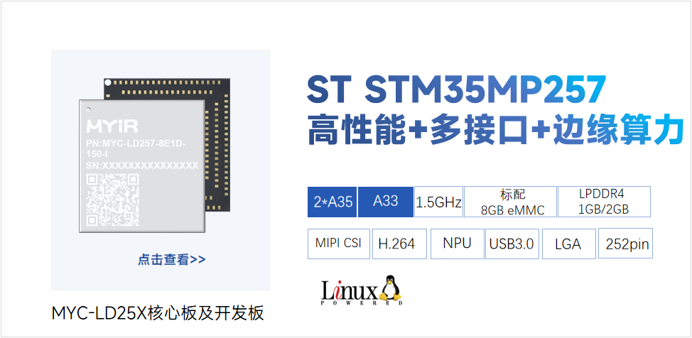
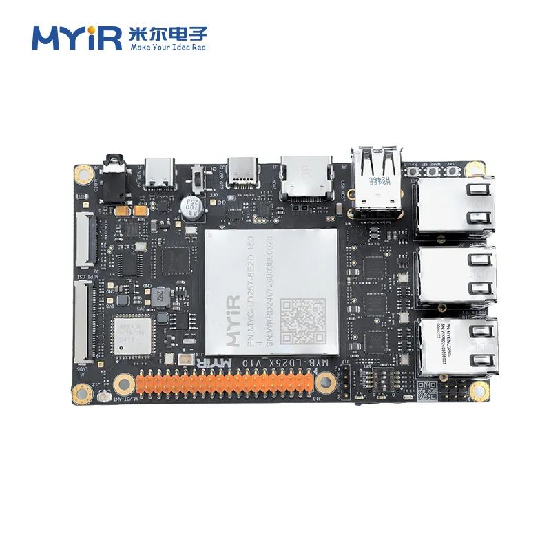
米尔基于STM32MP257核心板及开发板
3.USB启动
USB启动用于烧录镜像到外部flash,例如NAND,SD卡等,从PC端烧录镜像到外部 Flash是由U-Boot结合STM32CubeProgrammer完成的,配置并编译U-Boot是烧录的前提,根据STM32MPU的启动顺序:
TF-A->OP-TEE->U-BOOT->Linux Kernel
基本的启动流程如下图所示:
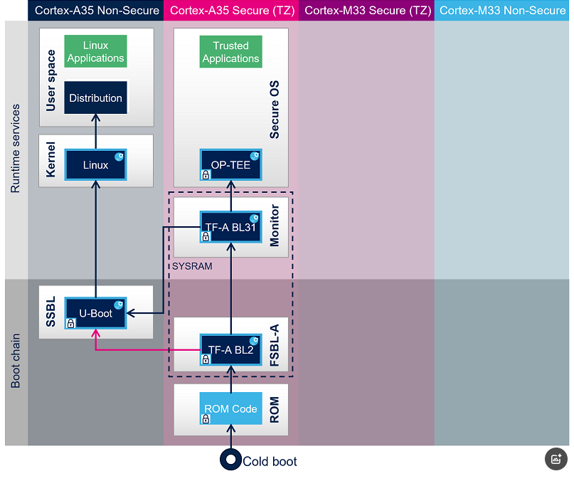
Linux 用户空间:应用程序。
3.1.TF-A的启动
进入到FIP_artifacts目录下
myir@myir-vm:~/stm32mp25x-BringUp-bsp/FIP_artifacts$ tree arm-trusted-firmware/ -L 1arm-trusted-firmware/├── bl31├── debug├── fwconfig├── metadata.bin├── tf-a-stm32mp257d-bringup-mx-optee-emmc.stm32└── tf-a-stm32mp257d-bringup-mx-usb.stm32
部署到开发板烧写环境(部署前请确认板子上电,串口线以及USB线正确连接):
将开发板拨码开关全部设置为0,接上USB OTG和电源,上电,测试连接环境
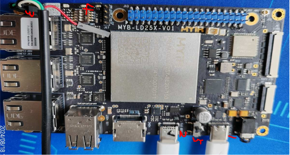
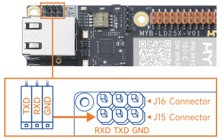
串口线连接J15接口:
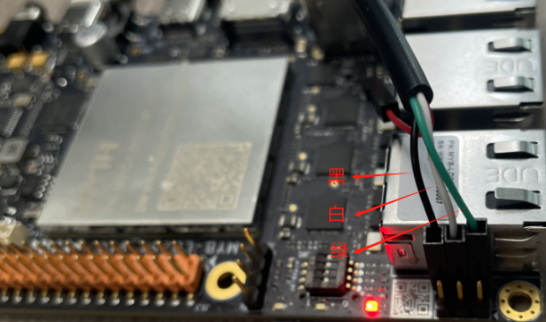
手动连接虚拟机

配置STM32cubeprogrammer环境
测试烧写环境
myir@myir-vm:~/stm32mp25x-BringUp-bsp$ STM32_Programmer_CLI -c port=usb1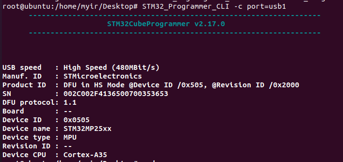
注意:如无法输入此命令,客户重新配置环境变量
myir@myir-vm:~/stm32mp25x-BringUp-bsp$ export PATH=$PATH:/home/myir/STMicroelectronics/STM32Cube/STM32CubeProgrammer/bin使用下列命令进行TF-a USB下载模式
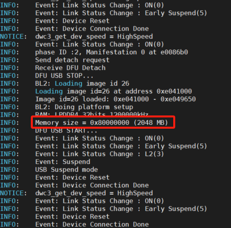
myir@myir-vm:~/stm32mp25x-BringUp-bsp$ cd FIP_artifactsmyir@myir-vm:~/stm32mp25x-BringUp-bsp/FIP_artifacts$ STM32_Programmer_CLI -c port=usb1 -d arm-trusted-firmware/tf-a-stm32mp257d-bringup-mx-usb.stm32 0x1 -s 0x1 -d fip/fip-stm32mp257d-bringup-mx-ddr-optee-emmc.bin 0x2 -s 0x2
3.2.Optee-OS和Uboot启动
使用下列命令进行FIP文件的烧写和启动
myir@myir-vm:~/stm32mp25x-BringUp-bsp$ cd FIP_artifactsmyir@myir-vm:~/stm32mp25x-BringUp-bsp/FIP_artifacts$ STM32_Programmer_CLI -c port=usb1 -d arm-trusted-firmware/tf-a-stm32mp257d-bringup-mx-usb.stm32 0x1 -s 0x1 -d fip/fip-stm32mp257d-bringup-mx-ddr-optee-emmc.bin 0x2 -s 0x2 -d fip/fip-stm32mp257d-bringup-mx-optee-emmc.bin 0x3 -s 0x3
注:执行该命令时板卡重新上下电。
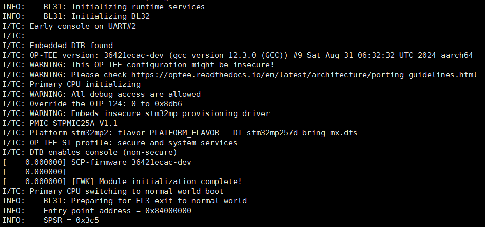
将生成的fip写到板子上,可以看到串口输出的optee-os的启动log如下:
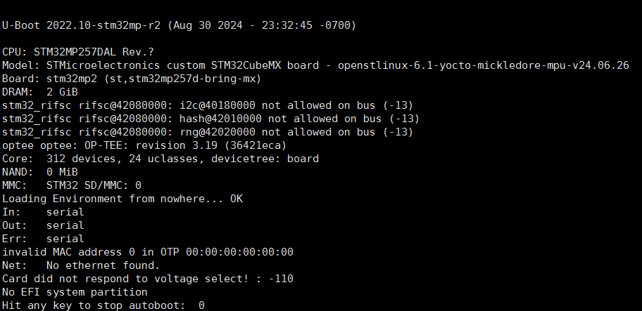
uboot的启动log如下
4.eMMC烧录与启动
4.1.TF-a和fip文件烧录emmc
在FIP_artifacts文件夹下创建一个tsv后缀的文件,命名:FlashLayout_emmc_stm32mp25x-bringup-mx.tsv填入如下内容。注意:这个TSV文件未定义内核和内核之后的内容
#Opt Id Name Type IP Offset Binary- 0x01 fsbl-boot Binary none 0x0 arm-trusted-firmware/tf-a-stm32mp257d-bringup-mx-usb.stm32- 0x02 fip-ddr FIP none 0x0 fip/fip-stm32mp257d-bringup-mx-ddr-optee-emmc.bin- 0x03 fip-boot FIP none 0x0 fip/fip-stm32mp257d-bringup-mx-optee-emmc.binP 0x04 fsbla1 Binary mmc0 boot1 arm-trusted-firmware/tf-a-stm32mp257d-bringup-mx-optee-emmc.stm32P 0x05 fsbla2 Binary mmc0 boot2 arm-trusted-firmware/tf-a-stm32mp257d-bringup-mx-optee-emmc.stm32P 0x06 metadata1 FWU_MDATA mmc0 0x00080000 arm-trusted-firmware/metadata.binP 0x07 metadata2 FWU_MDATA mmc0 0x00100000 arm-trusted-firmware/metadata.binP 0x08 fip-a FIP mmc0 0x00180000 fip/fip-stm32mp257d-bringup-mx-optee-emmc.binPED 0x09 fip-b FIP mmc0 0x00580000 nonePED 0x0A u-boot-env ENV mmc1 0x00980000 nonemyir@myir-vm:~/stm32mp25x-BringUp-bsp$ cd FIP_artifactsmyir@myir-vm:~/stm32mp25x-BringUp-bsp/FIP_artifacts$ STM32_Programmer_CLI -c port=usb1 -d FlashLayout_emmc_stm32mp25x-bringup-mx.tsv
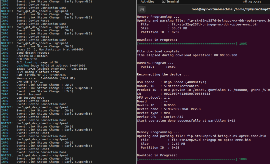
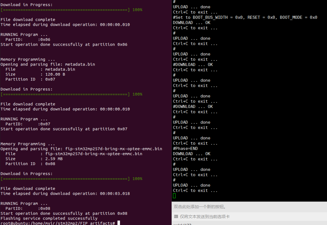
刷写log如下所示:
4.2.切换到emmc启动
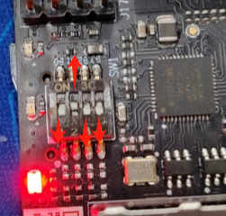
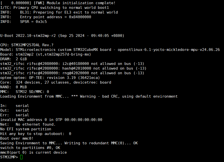
断电,将拨码开关切换到B0~B3(0 1 0 0)模式,重新上电即可emmc启动,启动log如下
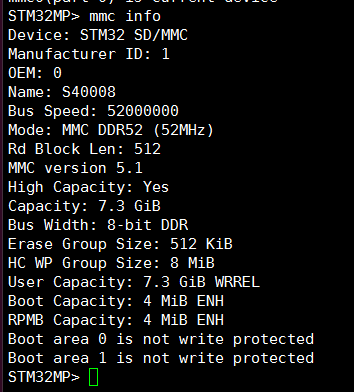
可在uboot终端下进行操作,如获取emmc信息命令mmc info
4.3.系统的整体烧录和启动
由于时间原因,编译整个内核代码和文件系统需要的时间很多,我们就先体验下整个系统的烧录和启动过程,后续可以查阅米尔的软件开发资料来详细了解Linux系统的启动过程。
在下载包里已经存在培训资料包里的myir-image-full文件夹里,使用STM32CubeProgrammer加载FlashLayout_emmc_myb-stm32mp257x-2GB-optee.tsv文件,后续的操作步骤在前面章节已经学会。
烧录时间较长(预计15分钟),完成后切换启动拨码开关到eMMC启动方式,即可上电进入整个Linux系统。
myir@myir-vm:~/myir-image-full$ STM32_Programmer_CLI -c port=usb1 -w ./flashlayout_myir-image-full/optee/FlashLayout_emmc_myb-stm32mp257x-2GB-optee.tsv
米尔电子最新“明星产品”速报
