做一个小项目 - 用小脚丫FPGA来测光,体会如何用全数字器件测量模拟信号。
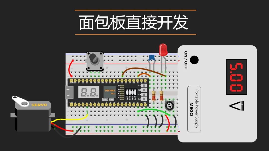
测量环境光的变化最简单、便宜的器件就是LDR,也称之为光敏电阻,适用于检测环境光的强度和环境的亮度。由于它体积小巧、便宜,易于使用,方便安装在面包板或者PCB上,被广泛用于各种创客产品中用作模拟传感器或环境光控制的开关来使用。可以通过MCU的ADC进行环境光亮度的测量,也可以通过电位计+比较器的方式通过MCU的数字IO进行感知。
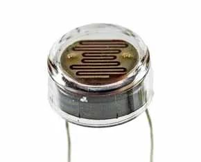
它的样子如下:
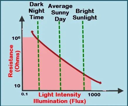
工作原理,就是不同的光强度下,其输出阻抗不同,典型曲线见下图:
如果按照下面的电路图连接,LDR两端的电压随着光线的强度增强而降低。
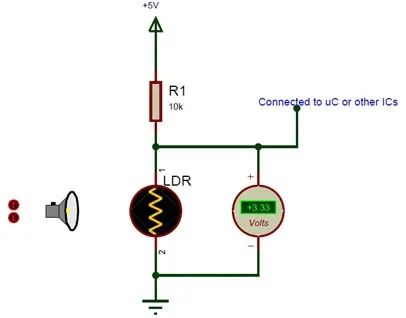
合理设定串接的电阻值,和LDR两端的电压的阈值,就可以通过LDR做光控开关,电路超级简单,但应用却非常广泛,比如生活中常用的:
我今天要介绍的是用小脚丫FPGA上的8个LED来指示环境光的强度,那就需要将LDR两端的电压信号进行量化。
问题来了,小脚丫FPGA是全数字的IO,板上没有模拟信号的入口,如果要采集外部的模拟量,那就需要用到模数转换器ADC,即便使用串行的ADC也会增加不少成本(比LDR要贵不少),还需要编写I2C或SPI的逻辑来将ADC的数据读出来。
有没有更偏移、更简单的方式呢?如果能够用价廉物美的方式读取外部的模拟信号,那很多没有数字接口的模拟传感器、电位计等都可以进行量化了。
答案是肯定的,只需要一个比较器和一个电阻/一个电容构成的低通滤波器就可以了,需要用到2个FPGA的IO,一个输出PWM信号,一个输入比较器的结果信号,用KiCad绘制一个简单的原理图:
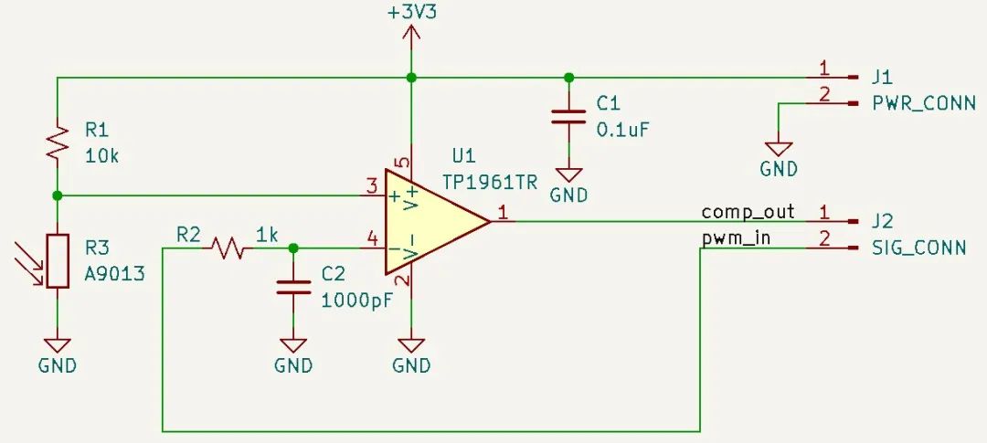
说明一下 - 原理图中的比较器用的是高速的,RC常数也选得截止频率比较高,是为了可以适配音频等频率有可能变化较快的信号(把图中的R3换成Micphone),在测量光强的场景下,光强的变化很缓慢,可以使用非常低速的比较器以及较低截止频率的RC参数。
绘图的时候不需要自己建库,KiCad系统自带的库已经非常丰富,可以直接拿来用:
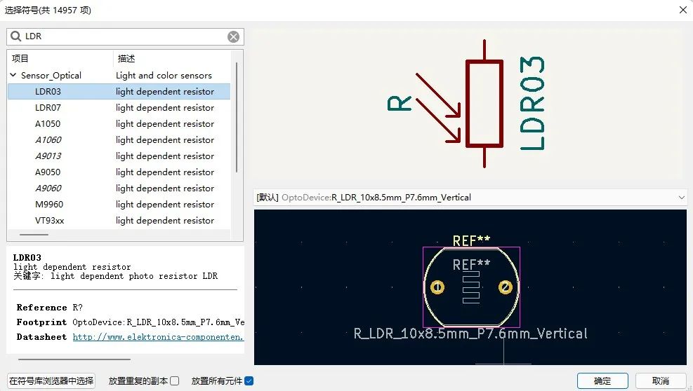
KiCad工具中有LDR的原理图符号、封装以及3D模型
最后做了一个小模块:
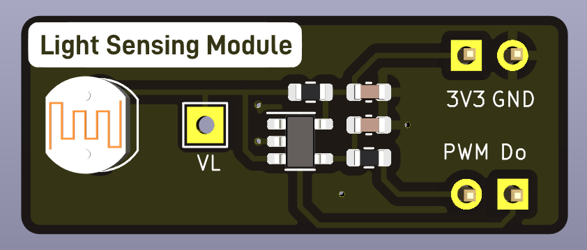
可以插在面包板上的模块的3D效果图
同小脚丫FPGA一起放在插到面包板上,并通过杜邦线将3.3V和GND连上,PWM和Do信号在面包板上自动连接。
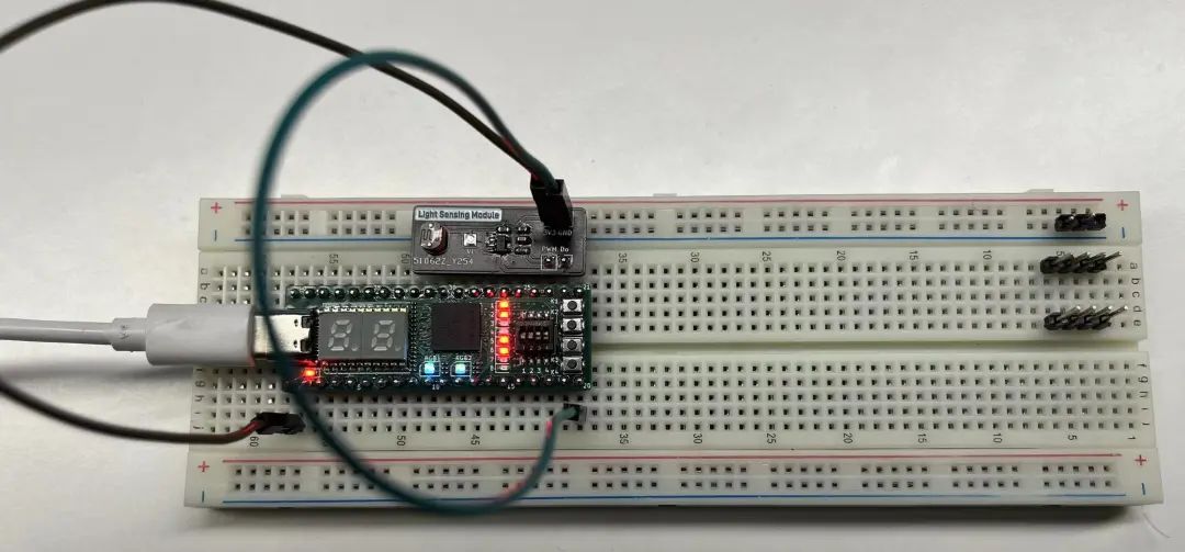
上图中的LED显示是已经下载了LDR检测代码的,随便用一个纸片或电路板对LDR进行遮挡,可以看到8个LED的变化。
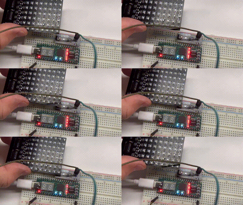
由于阻抗和光强的曲线不是线性的(但是单调的)如果要做更精准的测量,需要针对实际的曲线进行定标,比较简单的方式就是做一个查找表LUT,在FPGA里实现起来也非常简单。
有同学会问,用比较器和RC滤波器怎么就能测出来了?
其实这是利用了串行ADC的基本原理 - 1位的比较器,通过多次比较最终判断出准确的数字,在我们这个示例中用到的就是sigma delta方式的ADC。

详细的工作原理和实现代码在电子森林网站上都有(https://www.eetree.cn/project/detail/255),在这里不再赘述。
下面讲述一下编程:

编程使用我们的Web IDE也非常简单,根本不需要再安装任何软件,只需要打开网页www.stepfpga.com,登陆你自己已经创建好的账号,创建一个工程:
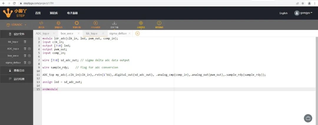
在网页里编写代码
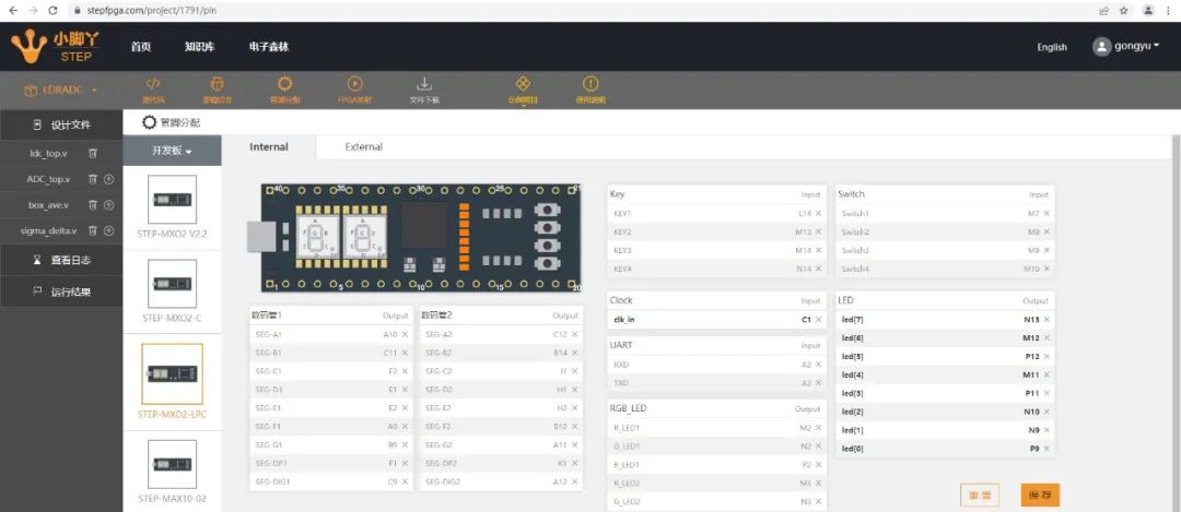
图形化管脚分配
Sigma Delta的顶层模块
module ADC_top (clk_in,rstn,digital_out,analog_cmp,analog_out,sample_rdy);parameterADC_WIDTH = 8, // ADC Convertor Bit PrecisionACCUM_BITS = 10, // 2^ACCUM_BITS is decimation rate of accumulatorLPF_DEPTH_BITS = 3, // 2^LPF_DEPTH_BITS is decimation rate of averagerINPUT_TOPOLOGY = 1; // 0: DIRECT: Analog input directly connected to + input of comparitor// 1: NETWORK:Analog input connected through R divider to - input of comp.//input portsinput clk_in; // 62.5Mhz on Control Demo boardinput rstn;input analog_cmp; // from LVDS buffer or external comparitor//output portsoutput analog_out; // feedback to RC networkoutput sample_rdy;output [7:0] digital_out; // connected to LED field on control demo bd.//**********************************************************************//// Internal Wire & Reg Signals////**********************************************************************wire clk;wire analog_out_i;wire sample_rdy_i;wire [ADC_WIDTH-1:0] digital_out_i;wire [ADC_WIDTH-1:0] digital_out_abs;assign clk = clk_in;//***********************************************************************//// SSD ADC using onboard LVDS buffer or external comparitor////***********************************************************************sigmadelta_adc #(.ADC_WIDTH(ADC_WIDTH),.ACCUM_BITS(ACCUM_BITS),.LPF_DEPTH_BITS(LPF_DEPTH_BITS))SSD_ADC(.clk(clk),.rstn(rstn),.analog_cmp(analog_cmp),.digital_out(digital_out_i),.analog_out(analog_out_i),.sample_rdy(sample_rdy_i));assign digital_out_abs = INPUT_TOPOLOGY ? ~digital_out_i : digital_out_i;//***********************************************************************//// output assignments////***********************************************************************assign digital_out = ~digital_out_abs; // invert bits for LED displayassign analog_out = analog_out_i;assign sample_rdy = sample_rdy_i;endmodule
Sigma Delta模块:
module sigmadelta_adc (clk,rstn,digital_out,analog_cmp,analog_out,sample_rdy);parameterADC_WIDTH = 8, // ADC Convertor Bit PrecisionACCUM_BITS = 10, // 2^ACCUM_BITS is decimation rate of accumulatorLPF_DEPTH_BITS = 3; // 2^LPF_DEPTH_BITS is decimation rate of averager//input portsinput clk; // sample rate clockinput rstn; // async reset, asserted lowinput analog_cmp ; // input from LVDS buffer (comparitor)//output portsoutput analog_out; // feedback to comparitor input RC circuitoutput sample_rdy; // digital_out is readyoutput [ADC_WIDTH-1:0] digital_out; // digital output word of ADC//**********************************************************************//// Internal Wire & Reg Signals////**********************************************************************reg delta; // captured comparitor outputreg [ACCUM_BITS-1:0] sigma; // running accumulator valuereg [ADC_WIDTH-1:0] accum; // latched accumulator valuereg [ACCUM_BITS-1:0] counter; // decimation counter for accumulatorreg rollover; // decimation counter terminal countreg accum_rdy; // latched accumulator value 'ready'//***********************************************************************//// SSD 'Analog' Input - PWM//// External Comparator Generates High/Low Value////***********************************************************************always @ (posedge clk)begindelta <= analog_cmp; // capture comparitor outputendassign analog_out = delta; // feedback to comparitor LPF//***********************************************************************//// Accumulator Stage//// Adds PWM positive pulses over accumulator period////***********************************************************************always @ (posedge clk or negedge rstn)beginif( ~rstn )beginsigma <= 0;accum <= 0;accum_rdy <= 0;end else beginif (rollover) begin// latch top ADC_WIDTH bits of sigma accumulator (drop LSBs)accum <= sigma[ACCUM_BITS-1:ACCUM_BITS-ADC_WIDTH];sigma <= delta; // reset accumulator, prime with current delta valueend else beginif (&sigma != 1'b1) // if not saturatedsigma <= sigma + delta; // accumulateendaccum_rdy <= rollover; // latch 'rdy' (to align with accum)endend//***********************************************************************//// Box filter Average//// Acts as simple decimating Low-Pass Filter////***********************************************************************box_ave #(.ADC_WIDTH(ADC_WIDTH),.LPF_DEPTH_BITS(LPF_DEPTH_BITS))box_ave (.clk(clk),.rstn(rstn),.sample(accum_rdy),.raw_data_in(accum),.ave_data_out(digital_out),.data_out_valid(sample_rdy));//************************************************************************//// Sample Control - Accumulator Timing////************************************************************************always @(posedge clk or negedge rstn)beginif( ~rstn ) begincounter <= 0;rollover <= 0;endelse begincounter <= counter + 1; // running countrollover <= &counter; // assert 'rollover' when counter is all 1'sendend
数字低通滤波器模块
module box_ave (clk,rstn,sample,raw_data_in,ave_data_out,data_out_valid);parameterADC_WIDTH = 8, // ADC Convertor Bit PrecisionLPF_DEPTH_BITS = 4; // 2^LPF_DEPTH_BITS is decimation rate of averager//input portsinput clk; // sample rate clockinput rstn; // async reset, asserted lowinput sample; // raw_data_in is good on rising edge,input [ADC_WIDTH-1:0] raw_data_in; // raw_data input//output portsoutput [ADC_WIDTH-1:0] ave_data_out; // ave data outputoutput data_out_valid; // ave_data_out is valid, single pulsereg [ADC_WIDTH-1:0] ave_data_out;//**********************************************************************//// Internal Wire & Reg Signals////**********************************************************************reg [ADC_WIDTH+LPF_DEPTH_BITS-1:0] accum; // accumulatorreg [LPF_DEPTH_BITS-1:0] count; // decimation countreg [ADC_WIDTH-1:0] raw_data_d1; // pipeline registerreg sample_d1, sample_d2; // pipeline registersreg result_valid; // accumulator result 'valid'wire accumulate; // sample rising edge detectedwire latch_result; // latch accumulator result//***********************************************************************//// Rising Edge Detection and data alignment pipelines////***********************************************************************always @(posedge clk or negedge rstn)beginif( ~rstn ) beginsample_d1 <= 0;sample_d2 <= 0;raw_data_d1 <= 0;result_valid <= 0;end else beginsample_d1 <= sample; // capture 'sample' inputsample_d2 <= sample_d1; // delay for edge detectionraw_data_d1 <= raw_data_in; // pipelineresult_valid <= latch_result; // pipeline for alignment with resultendendassign accumulate = sample_d1 && !sample_d2; // 'sample' rising_edge detectassign latch_result = accumulate && (count == 0); // latch accum. per decimation count//***********************************************************************//// Accumulator Depth counter////***********************************************************************always @(posedge clk or negedge rstn)beginif( ~rstn ) begincount <= 0;end else beginif (accumulate) count <= count + 1; // incr. count per each sampleendend//***********************************************************************//// Accumulator////***********************************************************************always @(posedge clk or negedge rstn)beginif( ~rstn ) beginaccum <= 0;end else beginif (accumulate)if(count == 0) // reset accumulatoraccum <= raw_data_d1; // prime with first valueelseaccum <= accum + raw_data_d1; // accumulateendend//***********************************************************************//// Latch Result//// ave = (summation of 'n' samples)/'n' is right shift when 'n' is power of two////***********************************************************************always @(posedge clk or negedge rstn)beginif( ~rstn ) beginave_data_out <= 0;end else if (latch_result) begin // at end of decimation period...ave_data_out <= accum >> LPF_DEPTH_BITS; // ... save accumulator/n resultendendassign data_out_valid = result_valid; // output assignmentendmodule
上述的3个文件虽然来自Lattice官网提供,但适用于所有的FPGA,我已经在多个不同的型号上尝试过,都能工作。
这个功能非常有用,在Lattice的FPGA上只占用了大约50个LUTS,可以以比较低的代价获得一个ADC的功能。
更多与数字电路相关的FPGA代码案例可以点击下面的小程序查看,页面中的案例需要跳转到www.stepfpga.com网站,可以通过H5直接访问: